
UNIVERSITY OF WEST ATTICA
SCHOOL OF ENGINEERING
DEPARTMENT OF COMPUTER ENGINEERING AND INFORMATICS
University of West Attica · Department of Computer Engineering and Informatics
Logic Design
Vasileios Evangelos Athanasiou
Student ID: 19390005
Supervision
Supervisor: Konstantinos Efstathiou, Professor
Supervisor: Ioannis Amorginos, Applications Lecturer
Co-supervisor: Eleni Tsalera, Academic Scholar
Co-supervisor: Anastasios Tsilikounas, Laboratory Teaching Staff
Athens, April 2021
This repository contains the documentation and implementation details for Workshop 2 of the Digital Design course at the University of West Attica, Department of Informatics and Computer Engineering.
The project focuses on the theoretical analysis, simulation, and implementation of basic arithmetic logic circuits used in digital systems.
| Section | Folder/File | Description |
|---|---|---|
| 1 | assign/ |
Assignment material for the Adders and Deductors workshop |
| 1.1 | assign/ASSIGNMENT 2.pdf |
Assignment description in English |
| 1.2 | assign/ΕΡΓΑΣΙΑ 2.pdf |
Assignment description in Greek |
| 2 | docs/ |
Documentation covering adders and deductors theory and implementations |
| 2.1 | docs/Adders-Deductors.pdf |
English documentation for adders and deductors |
| 2.2 | docs/Αθροιστές-Αφαιρέτες.pdf |
Greek documentation for adders and deductors |
| 3 | multisim/ |
Multisim circuit simulation files |
| 3.1 | multisim/semiAdder.ms14 |
Half (semi) adder circuit simulation |
| 3.2 | multisim/fullAdder.ms14 |
Full adder circuit simulation |
| 3.3 | multisim/semiDeductor.ms14 |
Half (semi) subtractor circuit simulation |
| 3.4 | multisim/fullDeductor.ms14 |
Full subtractor circuit simulation |
| 3.5 | multisim/adder4Bits.ms14 |
4-bit adder circuit simulation |
| 4 | README.md |
Project documentation |
| 5 | INSTALL.md |
Usage instructions |
The workshop covers the design and operation of four fundamental digital circuits used for binary arithmetic:
- Half Adder
- Half Subtractor
- Full Adder
- Full Subtractor
For each circuit, the project includes:
- Truth tables
- Logical equations
- Multisim simulations
- Physical implementation descriptions
The circuits were designed and simulated using NI Multisim.
- Logic Gates: AND, OR, NOR, NAND, XOR, XNOR, NOT
- Hardware Emulation Components:
- VCC sources (5V)
- Ground connections
- Wires
- Lamps (2.5V)
- Switches
- Measurement Tools:
- Oscilloscope for signal analysis
| Logic State | Voltage Range |
|---|---|
| Logic 0 | 0V – 0.5V (Ground) |
| Logic 1 | 2.7V – 5V (VCC) |
The Half Adder calculates the Sum (S) and Carry (C) of two one-bit binary inputs X and Y.
- Sum:
- Carry:
| X | Y | S (Sum) | C (Carry) |
|---|---|---|---|
| 0 | 0 | 0 | 0 |
| 1 | 0 | 1 | 0 |
| 0 | 1 | 1 | 0 |
| 1 | 1 | 0 | 1 |
The Half Subtractor calculates the Difference (D) and Borrow (B) between two one-bit binary inputs X and Y.
- Difference:
- Borrow:
| X | Y | D (Difference) | B (Borrow) |
|---|---|---|---|
| 0 | 0 | 0 | 0 |
| 1 | 0 | 1 | 0 |
| 0 | 1 | 1 | 1 |
| 1 | 1 | 0 | 0 |
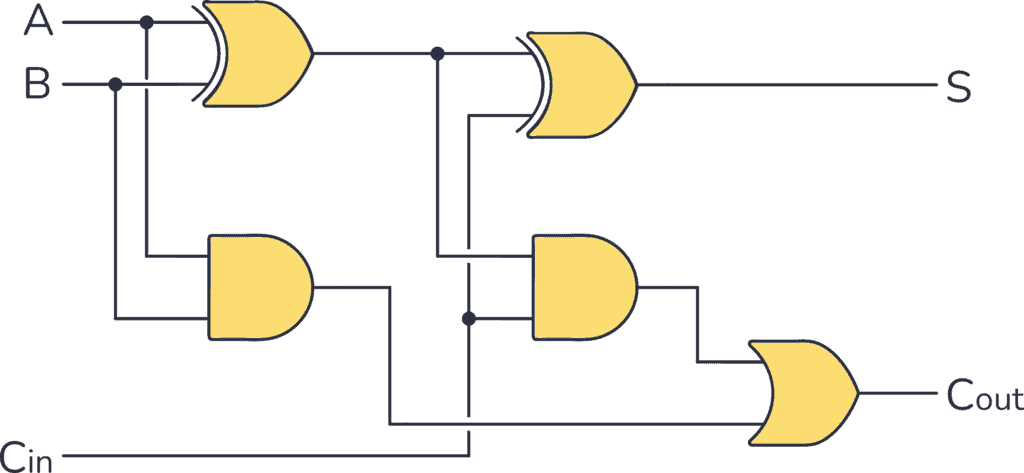
The Full Adder calculates the sum of three one-bit inputs: X, Y, and Carry-in (Cin).
Outputs:
- Sum (S)
- Carry-out (Cout)
Logical equations:
The Full Subtractor performs subtraction including a Borrow-in (Bin) input.
Outputs:
- Difference (D)
- Borrow-out (Bout)
Logical equations:
This workshop demonstrates the construction and operation of basic arithmetic circuits forming the foundation of Arithmetic Logic Units (ALUs) in modern processors. The simulations and implementations help reinforce understanding of binary arithmetic and digital circuit behavior.